Note: To provide some context, this report was for a final project in an undergraduate computer graphics course at the University of Texas at Austin. The final project was open-ended and I chose to extend a previous ray tracer assignment with simulated reflective diffraction grating. A C++ ray tracer framework was provided by the course, then completed and extended by me. The ray tracer code remains private to prevent scholastic dishonesty by future students who may stumble upon my project. This report only shows the results of my efforts.
Background
Diffraction is a beautiful phenomenon that causes iridescent lighting effects in materials. Diffraction happens when a planar wave encouters an obstacle or a slit. As shown in Figure 1, the planar wave bends around the corners. This phonomenon is a property of any type of wave. However, diffraction is generally talked about in terms of light. Light is a wave and will also bend around corners. If a slit decreases to a size comparable to the wavelength of light then the “wave” becomes spherical. Another way to look at it is the slit becomes a point source for the wave instead of a directional source.
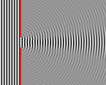 Figure 1: Planar wave (left) turning into a spherical wave (right) due to a small slit.
Most of the diffraction we see in the world happens on materials that have many small slits. Materials with many small slits are called diffraction gratings. Since every slit becomes a point source of light, diffraction gratings create a series of point lights close together. The combination of all of the waves causes interference, both constructive and destructive, and a pattern emerges. As shown in Figure 2, diffraction grating with multiple wavelengths of light will cause peaks of wavelengths at different viewing angles. The intensity of the light also falls off as the viewing angle is increased. This pattern is what we see when we look at a CD or certain meats.
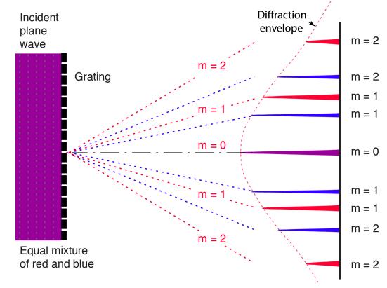 Figure 2: Planar wave (left) encountering a diffraction grating with many slits causing a pattern (right).
Current Work
Diffraction in graphics is an interesting problem to be solved in order to generate beautiful and photorealistic materials. Since photorealism is the goal, I use a ray tracer to implement diffraction. The ray tracer is a custom ray tracer built as an assignment in CS354. The ray tracer is extended to support diffraction materials.
Diffraction in a ray tracer works by simply adding a diffraction term to the Phong shading model. The computation of the diffraction term is derived by Emmanuel Agu and Francis Hill Jr. in their paper “A Simple Method for Ray Tracing Diffraction.” Agu and Hill derive two important equations that are called the Intensity Equation (Figure 3) and the Grating Equation (Figure 4). The intensity equation determines the intensity of light based on the viewing angles of a location and the wavelength of light. To determine what wavelengths of light are visible we use the grating equation.
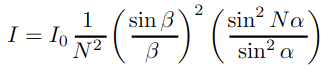
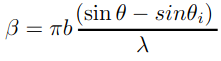
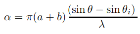 Figure 3: Intensity equation as a function of alpha and beta. Alpha and beta are functions of the viewing angles and the wavelength of light
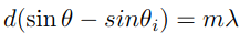 Figure 4: The grating equation gives us the wavelength of light that peaks at a given viewing angle.
Together, these two equations determine the total number of visible wavelengths and the total intensity which can then be added into the Phong shading model. However, the two equations above are derived in terms of light wavelengths. Computers use RGB triplets to represent color so a conversion between wavelength to RGB is necessary. There are many methods of conversion but I chose to convert wavelength to the CIE 1931 color space and then into sRGB triplets by means of interpolating from tabulated data.
In addition to the diffraction shading term, I extended the ray tracer to have tunable diffraction parameters. There are many constants involved in the intensity and grating equations. Here are the constants and their meaning in the equation:
- N = the number of slits per unit area
- a = the distance inbetween slits
- b = the width of a slit
- d = a+b, or also known as the total distance between the centers of each slit
The direction of the grating is also a tunable parameter. I modified the tokenizer and parser for the ray tracer and included these new parameters in the ray files. For the grating direction, my implementation allows for a single direction vector, a computed direction, or a map of direction vectors similar to a texture map. This allows for arbitrary diffraction gratings on any surface.
Results
Figures 1-8 are some artifacts produced by the new diffraction term. Some of these artifacts are demonstrating the change of a single parameter or differences in light. The dragon is simply showing how diffraction can now be applied to any mesh.
 Figure 5: Plate with diffraction grating. This shows an incremental change in the parameter d.
 Figure 6: Plate with diffraction grating. This shows an incremental change in the parameter n.
 Figure 7: Circular plate with a horizontal grating and a directional light.
 Figure 8: Circular plate with a horizontal grating and a point light.
 Figure 9: Circular plate with a radial grating and a directional light.
 Figure 10: Circular plate with a radial grating and a point light. This is the closest resemblence to diffraction on a CD.
 Figure 11: Diffraction grating on a trimesh of a dragon.
References
Agu, E., & S. Hill Jr, F. (2003). A Simple Method for Ray Tracing Diffraction (Vol. 2669, pp. 336–345). https://doi.org/10.1007/3-540-44842-X_35
Colour Rendering of Spectra. (n.d.). Retrieved November 17, 2018, from http://www.fourmilab.ch/documents/specrend/
Diffraction Grating. (n.d.). Retrieved December 5, 2018, from http://hyperphysics.phy-astr.gsu.edu/hbase/phyopt/grating.html
CIE Color System. (n.d.). Retrieved December 10, 2018, from http://hyperphysics.phy-astr.gsu.edu/hbase/vision/cie.html